Teensy PCB Ardumower (T-Mow)

Here is a small description of Components you will need:

BOOM File for PowerPCB
BOOM File for MainPCB
Be careful on some reference.

On power PCB:
No INA169 are needed :For sense motor and battery you need INA226 ->1 for battery and one for each motor ,so for 3D printer with 2 mow motor you need 5 INA226 and the 5 * R010 CMS resistor to replace the R100 one.

On Main PCB:
ESP32 DEV KIT V1 or perfectly pin compatible one.
GY-521 some PCB have the SDA and SCL not assigned like the PCB -> 3.3V/GND/SCL/SDA and not 3.3V/GND/SDA/SCL

R11 and LED 3V are not needed the ESP32 have a red one.

D7 you can replace by a shunt and take care in the +/- in the J25 5V connector .
If you use D7 you need to adjust DC/DC step down to have 5V at the output of the diode.

Remember that Code for teensy is actually in test !!
 
The ESP32 DEV V1 is now hard to get, at least here in Germany.
I think with a new version, it should be replaced with a normal ESP32 (38 pin version).

Right, I forgot about the R010 resistor. I still have to order them myself
Or buy ready ones with R010
I just need to find out how you did the GRD layers.
The SB1240s don't fit in the holes on the board either.
So there are certainly a few improvements that can be made.
I hope the boards don't take too long to get here.
 
Last edited:
Thanks Bernard und Sascha ! very nice from you to share your project ! :) I will take care about all recommendations you give and I will go step by step.
Thanks Sascha for the two files with needed material. :)
 
On Main PCB:
ESP32 DEV KIT V1 or perfectly pin compatible one.
GY-521 some PCB have the SDA and SCL not assigned like the PCB -> 3.3V/GND/SCL/SDA and not 3.3V/GND/SDA/SCL

R11 and LED 3V are not needed the ESP32 have a red one.

D7 you can replace by a shunt and take care in the +/- in the J25 5V connector .
If you use D7 you need to adjust DC/DC step down to have 5V at the output of the diode.

Remember that Code for teensy is actually in test !!
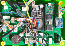
GY-521 / U2 => thisone should be ok ?
ESP32, yes, not really easy to find.
Right, I forgot about the R010 resistor. I still have to order them myself
Or buy ready ones with R010
I just need to find out how you did the GRD layers.
Keep care Sascha, thoseones from your link have wrong connections: SLC/SDA, seems to be inverted.
Maybe thisones, but the R100 must be changed ?
 
Compared with INA226, Vin+/Vin- are inverted (output side), maybe PCB should be adapted.

Well, thoseones from my link are for sure bad in quality.
 
Last edited:
Compared with INA226, Vin+/Vin- are inverted (output side), maybe PCB should be adapted.

Well, thoseones from my link are for sure bad in quality.
Yes but this is a quick change. And for boards that have already been purchased, it would be sufficient to swap plus and minus at the connections.
The code changes are also quickly made.
Let's see what Bernard says.
 
I must take a look at the PowerPCB when i'm at home. Perhaps the Traces on the PCB must also change.
 
GY-521 / U2 => thisone should be ok ?
ESP32, yes, not really easy to find.

Keep care Sascha, thoseones from your link have wrong connections: SLC/SDA, seems to be inverted.
Maybe thisones, but the R100 must be changed ?
What you suggest is OK.

Gy-521 perfect
mainpcb.png
INA-226 perfect : SCL and SDA are in the correct order (U1 U2 U6 are on the same i2c0 line and U3 U4 U5 are on I2C1, so it's possible to directly invert the wire in the J5 connector )

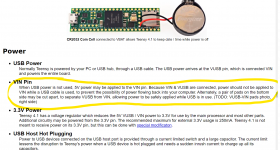
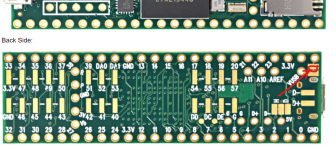
For main PCB it's good to first test everything powered with your PC via USB (no 5V at the moment on J25) and when all is OK with your phone and arduremote you can CUT THE PAD SHUNT AT THE BACK of Teensy .
After cutting the pad shunt you need to power PCB using 5V at J25 and you can plug the USB cable to your PC without issue.
powerteensy.pngpad to cut.png
 
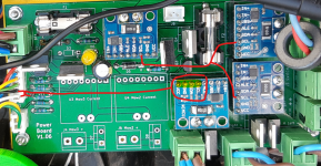
Here picture of my first PowerPCB with 2 kind of INA226 scl sda mapping.
But it's not a problem you need to have at least 3 module with same wiring
ina226.png
 
Ok, Bernard, many things to write on the to do list thanks ! :)
To stay in "a standard" I will order 5X the sames INA226.
 
Last edited:
Hi Sascha and Bernard, I spent many hours to find electronic parts and finally, most of thoseones are from Reichelt. Didn't find the right ESP32 for now, but I hope my list is correct.
I didn't managed to add my excel document.
 
Hi Sascha, I will watch your link, it would be perfect, thanks ! I made a zip file. If you have a moment to controle if it's ok, but no stress :D
 

Attachments

After a quick look, not all electronic parts seems to be right.
I hope you haven't ordered yet? Then I will create a list for you later.
Have you already decided on Motors?
Brushed Motors/ Brushless Motors?
 
I haven't ordered yet. I think about Brushless Motors, but I absolutly don't know what and where to order thosones :D. Thanks for your help and have a nice week-end.
 
Last edited:
Good news, PCB's have been sended from jlcpcb :) .
Ultra sonic sensors have also to be added.
 
Last edited:
I haven't ordered yet. I think about Brushless Motors, but I absolutly don't know what and where to order thosones :D. Thanks for your help and have a nice week-end.
Actual software work only for DC motor (you need to add code for BL Motor)
Issue is in the driver and the odometry.
 
Back
Top