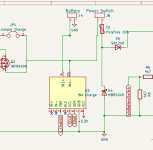
PowerPCB 1.09

Hallo Sascha,

habe heute meinen Power PCB ausgepackt. Das erste was auffällt die Beschriftungen SDA SCL bei den INAs sind einmal gedreht. Oder habe ich andere INA226 als Ihr.

Gruß
Alexander
 
Last edited:
Dann musst du darauf achten, die Kabel an dem Anschluss zu drehen, so daß es wieder passt.
Leider gibt es da Unterschiede INAs
 
Weil das einfacher war mit der Adressvergabe auf den Inas.
Die 3 Pads auf der Rückseite lassen nicht so viele Adressen zu, ansonsten müsste man an verschieden Pins gehen, um die Adresse einzustellen
 
Ich habe noch eine Verständnisfrage. Im Batteriebetrieb wird der Strom der an J11 und J12 angeschlossenen Verbraucher mit keinem der INA's gemessen. Richtig? Hängt da nicht normallerweise der Teensy Board dran?
 
In meinen Augen könnte man das relativ einfach lösen in dem man Batterie an IN+ und Charger an IN- (die Leitung zum Power switch bleibt an IN-) anschliesst. Im Batteriebetrib ist der Strom über INA positiv im Ladebetrieb negativ
 

J11 and J12 are used to power 2 DC/DC 24/5V voltage regulator:
One for teensy and the other for raspberry Pi
And no need to manage the sense on these connector ,Only on Motor and charge battery
 
 
J11 and J12 are used to power 2 DC/DC 24/5V voltage regulator:
One for teensy and the other for raspberry Pi
And no need to manage the sense on these connector ,Only on Motor and charge battery
In this case will Cassandra or whatever visualization you are using show 0A in idle mode, and it is simple wrong.
 
In this case will Cassandra or whatever visualization you are using show 0A in idle mode, and it is simple wrong.
Yes if you use J11 or J12 to connect electronics.
But if your mower have only 3 motors you can use the motor4 or motor5 output to manage the sense of the other electronics component
It's like you want.
 
Just my suggestion how to solve that in future, no extra hardware needed, just change wiring of IN+ and IN-

In your suggestion I‘ll need additional INA226
 
Just my suggestion how to solve that in future, no extra hardware needed, just change wiring of IN+ and IN-

In your suggestion I‘ll need additional INA226
Yes.
Can you explain a little more your suggestion IN+ / IN- ,i don't understand it
 
Maybe it's also possible to use only one I2C line , but need test on particular shunt on the INA226 PCB
 
I am always open to suggestions and improvements, there are certainly one or two things that can be done better.
 
I think so:
1707065059900.png

I don't know how you trigger charger connected in the software, but now you have to check if measured current is negative or not.
 
Back
Top