You are using an out of date browser. It may not display this or other websites correctly.
You should upgrade or use an alternative browser.
You should upgrade or use an alternative browser.
Matrix MOW800
- Thread starter Sascha
- Start date
Fürst Ruprecht
Well-known member
bei mir geht es von Vbatt auf 5V-Spannungsregler und dann auf einen kleineren 3,3V-Regler und erst dann zum Teensy und den anderen Chips.
Sollte der 5V-Regler versagen, was nicht unwahrscheinlich ist, dann hält der 3,3V-Regler das trotzdem noch aus. Ein loses Kabel ist damit aber trotzdem möglich.
Bei Deiner Schaltung ist dann d1 eine Opferdiode.
Ich habe mich über die zwei Poties auf meinem Regler gewundert. Das zweite ist tatsächlich die Strombegrenzung, nicht schlecht für ein Chinamodul. Alle anderen vorher hatten das nicht.
Ja so war ist es gedacht, wenigstens ein kleiner Schutz.
Jetzt muss ich nur noch eine Lösung für die PowerPCB finden, ich verstehe nämlich nicht, das bei mir der Unterspannungs Abschaltung nicht funktioniert bzw. immer nur einmal und dann schaltet das Board nicht mehr ab.
Bei der Ladeschaltung, funktioniert das ohne Probleme und es ist die gleiche Schaltung.
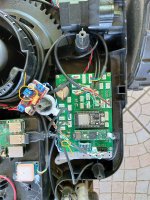
I don't know if it can protect the main pcb but i use a DC/DC with limited sense.
The issue : how to adjust it
The 5V input diode is shunt for me but it's possible to use a polyfuse at 500ma instead and a 5V zener diode
A 5A polyfuse is actualy in test in my 2 platforms on the power PCB to avoid openning the chassis when fuse burn, You can see it in the picture of my previous post ,locate near the heat sink .
I have simply solder it on an old fuse.
The issue : how to adjust it

The 5V input diode is shunt for me but it's possible to use a polyfuse at 500ma instead and a 5V zener diode
A 5A polyfuse is actualy in test in my 2 platforms on the power PCB to avoid openning the chassis when fuse burn, You can see it in the picture of my previous post ,locate near the heat sink .
I have simply solder it on an old fuse.
What do you mean by the ~No it is by ~70-120
it's -70 to -120 or from +70 to -120

