Start Probleme

Hello, oh man who can read... Thank you very much.

So I've gone through a lot now.
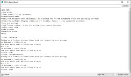
Appears to have a problem with odometry during engine calibration.
I also get keune ticks right or left displayed. Is there something wrong?

Also, it seems to me that there is something wrong with the attitude. it feels like it drives 10m in the odometry test "1 Turn Wheel Fwd"
Shouldn't he make a turn of the wheel....
 

Attachments

  • Screenshot 2023-05-01 135317.jpg
    Screenshot 2023-05-01 135317.jpg
    106.3 KB · Views: 9
Last edited:
Use arduremote for all test.
First and important step is the odo test "1 Turn Wheel Fwd"
If it's not OK you need to adjust the odometry setting.
Into motor setting set the speed max in pwm to 100 for a slow test.
Now into odometry setting adjust ticks per one full revolution until you have the test odo "1 Turn Wheel Fwd" OK
 
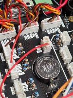
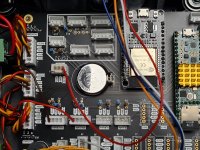
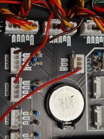
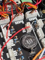
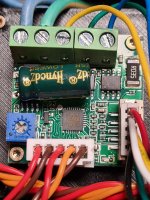
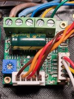
It's hardware issue Odometry is not working ,can you show me how did you connect the motor driver to PCB ?
 
It's hardware issue Odometry is not working ,can you show me how did you connect the motor driver to PCB ?
Yes i can...
 

Attachments

  • 20230501_183043.jpg
    20230501_183043.jpg
    898.2 KB · Views: 8
  • 20230501_182843.jpg
    20230501_182843.jpg
    999.3 KB · Views: 7
  • 20230501_183037.jpg
    20230501_183037.jpg
    861.7 KB · Views: 7
  • 20230501_183043.jpg
    20230501_183043.jpg
    898.2 KB · Views: 9
  • 20230501_183726.jpg
    20230501_183726.jpg
    909.9 KB · Views: 8
  • 20230501_183713.jpg
    20230501_183713.jpg
    946.8 KB · Views: 9
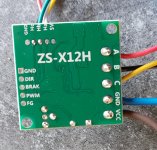
I need the driver side picture to see , and your wire have same color , but you need to connect
zs-x12h 20.jpg
PCB MOTOR -----> Driver
+ --------> nothing
GND ---------> GND
PWM ----------> PWM
DIR ---------> DIR
EN ------->nothing
BRAKE --------> BRAK

PCB Odo_Left ------> driver
GND --------> nothing
5V --------> nothing
3.3V --------> nothing
SIG --------> FG


check again and try to see if you have altrnative 5V and 0V on FG driver pin when motor rotate at very very very low speed
 
yes i know that sorry but i measured them and i connected everything as you described. I'll measure the sig pin now...
 
It's not OK .
Normaly it's more than 300 ticks per rev , so to see the change using a multimeter it's very hard ,or the motor need to rotate very very very slowly
You don't need to connect the PCB part to test only between the FG pin and GND

Do you have a scope ?
 
It's not OK .
Normaly it's more than 300 ticks per rev , so to see the change using a multimeter it's very hard ,or the motor need to rotate very very very slowly
You don't need to connect the PCB part to test only between the FG pin and GND

Do you have a scope ?
No only this "Multimeter"
 
Try to not connect the driver to PCB and use the blue poti to see the wheel rotate at the lower possible speed.
Check the voltage at FG to see if it change.
Also you can try to move the wheel by hand , but it's one change each less than 0.5 degres ,so very difficult to see
 
Try to not connect the driver to PCB and use the blue poti to see the wheel rotate at the lower possible speed.
Check the voltage at FG to see if it change.
Also you can try to move the wheel by hand , but it's one change each less than 0.5 degres ,so very difficult to see
Ok i test it tomorow, many thanks bernard....
 
Ok i test it tomorow, many thanks bernard....
ok
so just measured the driver and increased the value with the little blue podi, i measure a very clean 4.8v when it is standing and 2.4v when it is moving.
without current fluctuations
 
Maybe check R1 R2 R7 R8 value and soldering ???
Or test to see if you have ticks with define MI632

Code:
//**************************************************************
// ------- select one platform type -------------------
//**************************************************************
#define MI632
//#define YARDFORCE
//#define RL2000
//#define MOW800

Hello,
I checked and measured everything.
Wiring is ok. According to bom, the Resistors are r1 + r2 = 2 kohm and r7 + r8 = 1 kohm. The speed current from the driver is also good with 4.8v, only on the board it is then pulled down to a maximum of 1v or below, where it then goes to teensy.
I also have tested the configuration for MI632 but it didn't change anything.
 
Back
Top