PowerPCB 1.09

Just for testing, I quickly uploaded a FW to see what I get for testing. Now that I've set up a little what I need, I get a lot of errors. Anyway, I am going to rebuild a Bosch Indego 800 machine. What is important is that there will be 2 perimeters and all engines will be driven by the BTS7960 Driver. It will also include 3 ultrasound sensors.
is it feasible to have a 240x320 SPI display on the teensy?
It's warning ,you can deactivate them into arduino ide Capture d'écran 2024-05-27 123042.png

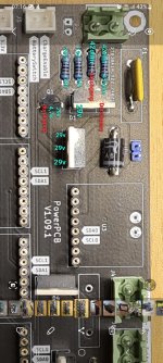
For Bosh , you need to first select the correct platform , but we never build it , so you can start with RL2000 and i select correct PCB version.

Into mower.h

Code:
//**************************************************************
// ------- select one platform type -------------------
//**************************************************************
//#define MI632
//#define YARDFORCE
#define RL2000
//#define MOW800

//**************************************************************
// ------- select one mainPCB -------------------
//**************************************************************
//#define PCB_V101
#define PCB_V103

Also if you have only 1 mow motor you need to deactivate the Mow2 and 3 INA226 :

Code:
#if defined (RL2000)  // here all setting for YARDFORCE
//*****************possible list of motor driver set to :****************
// 1 for brushless ZS-X11H v1 Driver
// 2 for DC L298N Driver
// 3 for DC BTS7960 Driver
#define LEFT_MOTOR_DRIVER 3  //never mix BL and DC on drive motor
#define RIGHT_MOTOR_DRIVER 3
#define MOW_MOTOR_DRIVER 3

#define BUMPER_IS_SWITCH true  // set to true if the bumper is a single ON/OFF switch
#define BUMPER_REAR_EXIST false  // set to true to manage the rear bumper connected on CAN3 J20 connector
#define BUMPER_ARE_NORMALY_CLOSED false  // set to true if the bumper contact is closed when nothing is hit

#define START_BUTTON_IS_NC false //if button is normaly closed

// mower can have a cover that stop the mowing cycle but power still on the PCB,mower only start after closing the cover
// start button is under cover , so after push the start button you have 10 seconde to close cover and mower start
// openning the cover stop mowing cycle
#define MOWER_HAVE_SECURITY_COVER false // mower can have a cover that stop the mowing cycle but power still on the PCB,mower only start after closing the cover

#define INA226_MOW2_PRESENT false
#define INA226_MOW3_PRESENT false

#define ODOMETRY_ONLY_RISING false
#endif


3 ultrasound sensors
Only 2 sensors are possible on MainPcb

is it feasible to have a 240x320 SPI display on the teensy?
SPI in not actually wire on the MainPcb.
Code is also no present.
Only OLED Screen is actually possible on I2C bus.

But certainly Teensy 4.1 can manage this kind of screen

For real HMI it's better to use Raspberry Pi and PiArdu.
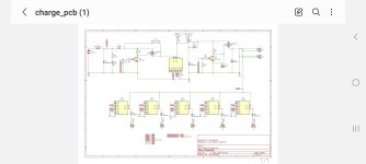
Code and wiki are here.


Hello, I probably have a problem with the new powerboard. Apparently it doesn't let any charging current through. No charging current is displayed in the app but the voltage display works. The blocking diode is also the right way round. what could it possibly be?

Hallo ich habe wahrscheinlich ein problem mit dem neuen Powerboard.
Er lässt anscheinend kein Ladestrom durch.
In der app wird auch kein Ladestrom angezeigt aber die Voltanzeige funktioniert.
Die Sperrdiode ist auch Richtig herum. woran könnte es denn evtl. liegen?
 
Die LED leuchtet auch nicht, wenn er laden soll?
Wenn es mit Jumper auch nicht funktioniert, vielleicht die Sicherung defekt?
 
Hmm, nein leider nicht. Ich habe sie vieleicht ein bis zweimal leuchten sehen. Also an die Lade Kontakte gehalten, dann hatt sie geleuchtet. Dann wieder ab und wieder drann dann macht sie nichts mehr.

Sicherung hatte ich auch schon gedacht und sie mal gebrückt aber keine Chance. Ich muss heut mal alles durch messen. Irgendwas stimmt nicht.
Ansonsten läuft alles wunderbar....
 
Dann mal die genannten Teile durchmessen.
Auch den Netzteil prüfen ob er liefert. Wenn die genannten Halbleiter einen Kurzschluss gemacht haben, kann sein dass der Netzteil im Schutzmodus ist oder die Sicherung im Netzteil durch ist. Oder, oder.
 
Ok, na netzteil ist ok.
Ich lade den Mäher jetzt immer direkt am Akku Anschluss mit dem selben Netzteil.
Bis ich bzw. Wir den Fehler gefunden haben.

Ja messen ich werde...
 
So ich habe mal alle Punkte durchgemessen ich hoffe mann sieht hier durch. Ladestrom an den frontbuchsen liegt an und jumper ist gesetzt.
Aber irgendwas stimmt hier gar nicht glaube ich...
 

Attachments

  • Screenshot_20240625_071629_Gallery.jpg
    Screenshot_20240625_071629_Gallery.jpg
    709.8 KB · Views: 22
Ich verstehe zwar nicht ganz wie du gemessen hast, aber ich vermute stark dass Q2 durchgebrannt ist und einen Kurzschluss hat.
Prüfe mal ohne Strom. Multimeter in Diodenstellung. Q2 darf zwischen keinen den Beinen einen Kurzschluss haben und nur von Drain zu Source hat einen Diodendurchgang (ca. 0,5).
 
Sorry ich habe beim ladeeingang einmal Masse angesetzt und bin dann Stück für Stück die Bauteile abgegangen.

Ja das kann ich machen danke dir...
 
So ich habe mal Pauschal q1 und q2 getauscht. Aber leider kein Unterschied, Led funktioniert erst wunderbar aber in der App bekomme ich noch keinen Ladezustand bei Battery Charge, ergo weiß er nicht ob er in der Station ist oder nicht. Sehr seltsam. Könnte es evtl. an der INA liegen?

Heut Morgen nochmal getestet und keine LED mehr und beim messen was hinten an der Ladebuchse rauskommt, habe ich leider auch nur eine ohm Anzeige die sich verändert wenn ich vorn Strom anlege?

Ich muss mich heut abend nochmal damit beschäftigen, kann doch ni so kompliziert sein. Soviel ist doch da nicht dazu!
 

Attachments

  • Screenshot_20240627_080316_Samsung Notes.jpg
    Screenshot_20240627_080316_Samsung Notes.jpg
    315 KB · Views: 13
Last edited:
Kleines Update, das mit dem Led leuchtet und mal nicht, habe ich gelöst. Es lag an einem korodiertem Anschluss an den Ladeplatten vorn. Also Ladestrom habe ich jetzt bis zum Akku.
Jetzt fehlt mir nur noch die Meldung im System das er geladen wird!? Das müsste ja von der Ina kommen oder?
 
Take a look at your battery setting.
You need to see all the voltage (battery / station and sense if charging is in process).
If battery is not in charging process (no sense)
Adjust the start charging voltage to see the state change and charging start when you set a high value
 
And my problem with the powerboard is solved. A defective blocking diode D3 was to blame for charging not working. Changed and now everything is good. All functions are present, with jumper it always charges. Without a jumper, it only charges via the board or Teensy.

Und mein Problem mit dem Powerboard ist gelöst.
Eine defekte Sperrdiode D3 war schuld, das es nicht funktioniert hatt mit dem Laden. Gewechselt und jetzt ist alles gut.
Alle funktinonen sind gegeben, mit jumper lädt er immer. Ohne Jumper lädt er nur über das Board bzw. Teensy.
 
Last edited:
In my battery voltage meauserments I see some voltage jumps (+- 0.4V). Is that something coming from INA or is that something else?
Bildschirmfoto vom 2024-07-30 14-06-09.png
 
Back
Top