PowerPCB 1.09

Hello!

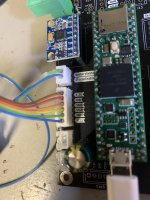
I’m new to the forum. I had the latest version of the PCBs manufactured from GitHub. I followed all the instructions. Instead of the battery, I connected a 24V power supply, but it doesn’t display the voltage. It shows only 0.1V. What could be the issue, and what should I pay attention to? The boards I’m using are the Teensy_MainPCB_V1.03 and the Power_PCB_v109.

Thank you in advance for your help! (I’m Hungarian, and my English is not very good.) 😊
 
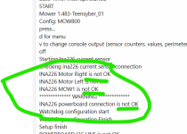
I get this message. I did everything as described.

SETUP
++++++++++++++ Start Robot Setup at 2301.00 ++++++++++++
Initialise date time library
RTC has set the system time
------------------- Initializing SD card... ---------------------
SD Card failed, or not present
Version : 1.483-Teensyber_01
Pfod connection initialisation at : 19200
Load ErrorData Address Start= 500.00 Stop= 522.00
UserSettings OK from Address : 2000.00 To 2496.00
Save Stats Adress Start = 800.00 Stop = 826.00
IMU: found calib data
Load Calibration
Calibration address Start = 600
Calibration address Stop = 650
-------- IMU CALIBRATION --------
ACCEL GYRO MPU6050 OFFSET ax: -1790 ay: -930 az: 1750 gx: -236 gy: -10 gz: 8
COMPASS OFFSET X.Y.Z AND SCALE X.Y.Z
comOfs=0.00,0.00,0.00
comScale=2.00,2.00,2.00
.
--------------------------------- GYRO ACCEL INITIALISATION ---------------
MPU6050 connection successful
52
Initializing DMP...
Enabling DMP... Packet size 28
Wait 3 secondes to stabilize the Drift
AccelGyro Yaw: -0.00--------------------------------- IMU READY ------------------------------
------- Initialize Perimeter Setting -------
Begin setup adc0 on pin:23
End setup adc0
Try to Start adc0 Timer Interrupt
adc0 Timer Interrupt Started
START
Mower 1.483-Teensyber_01
Config: MOW800
press...
d for menu
v to change console output (sensor counters, values, perimeter etc.)
off
Starting Ina226 current sensor
Checking ina226 current sensor connection
INA226 Motor Right is not OK
INA226 Motor Left is not OK
INA226 MOW1 is not OK
************** WARNING **************
INA226 powerboard connection is not OK
Watchdog configuration start
Watchdog configuration Finish
Setup finish
POWERBOARD I2C LINE is not OK
Error IMU read duration >30 ms : 2710.00
IMU and RFID are DEACTIVATE Mow in safe mode
------ LOOP NOT OK DUE IS OVERLOAD -- Over 1 sec 1896.00
 
PowerPCB and MainPCB are connected?
Can you Test a I2c Scanner in the Teensy to see If the INAs could be found?
 
I get this message. I did everything as described.

SETUP
++++++++++++++ Start Robot Setup at 2301.00 ++++++++++++
Initialise date time library
RTC has set the system time
------------------- Initializing SD card... ---------------------
SD Card failed, or not present
Version : 1.483-Teensyber_01
Pfod connection initialisation at : 19200
Load ErrorData Address Start= 500.00 Stop= 522.00
UserSettings OK from Address : 2000.00 To 2496.00
Save Stats Adress Start = 800.00 Stop = 826.00
IMU: found calib data
Load Calibration
Calibration address Start = 600
Calibration address Stop = 650
-------- IMU CALIBRATION --------
ACCEL GYRO MPU6050 OFFSET ax: -1790 ay: -930 az: 1750 gx: -236 gy: -10 gz: 8
COMPASS OFFSET X.Y.Z AND SCALE X.Y.Z
comOfs=0.00,0.00,0.00
comScale=2.00,2.00,2.00
.
--------------------------------- GYRO ACCEL INITIALISATION ---------------
MPU6050 connection successful
52
Initializing DMP...
Enabling DMP... Packet size 28
Wait 3 secondes to stabilize the Drift
AccelGyro Yaw: -0.00--------------------------------- IMU READY ------------------------------
------- Initialize Perimeter Setting -------
Begin setup adc0 on pin:23
End setup adc0
Try to Start adc0 Timer Interrupt
adc0 Timer Interrupt Started
START
Mower 1.483-Teensyber_01
Config: MOW800
press...
d for menu
v to change console output (sensor counters, values, perimeter etc.)
off
Starting Ina226 current sensor
Checking ina226 current sensor connection
INA226 Motor Right is not OK
INA226 Motor Left is not OK
INA226 MOW1 is not OK
************** WARNING **************
INA226 powerboard connection is not OK
Watchdog configuration start
Watchdog configuration Finish
Setup finish
POWERBOARD I2C LINE is not OK
Error IMU read duration >30 ms : 2710.00
IMU and RFID are DEACTIVATE Mow in safe mode
------ LOOP NOT OK DUE IS OVERLOAD -- Over 1 sec 1896.00
Capture d'écran 2024-05-17 190559.png

Did you have the shunt on the INA226 ??
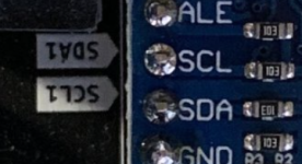
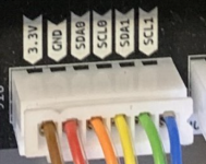
It YES : Try to swap SDL / SDA in the connector between POWER PCB and MAIN PCB
 
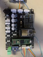
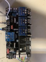
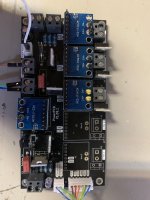
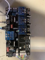
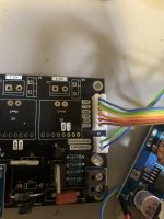
I have attached a picture of how the bridges are.
SDL / SDA is properly connected.
 

Attachments

  • unnamed (2).jpg
    unnamed (2).jpg
    1 MB · Views: 18
  • unnamed (1).jpg
    unnamed (1).jpg
    865.4 KB · Views: 17
  • unnamed.jpg
    unnamed.jpg
    828.2 KB · Views: 16
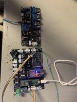
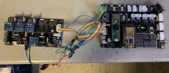
Please take a picture of the wiring (includind the DC/DC 24 to 5V)
WARNING : adjust the DC/DC stepdown to 5V before connecting the mainPCB or you can burn everything.

SDA and SCL certainly need a swap between powerPCB and mainPCB according your version of INA226

Capture d'écran 2024-05-17 200423.png

swap here
Capture d'écran 2024-05-17 200703.png
 
Please take a picture of the wiring (includind the DC/DC 24 to 5V)
WARNING : adjust the DC/DC stepdown to 5V before connecting the mainPCB or you can burn everything.

I supply 24 volts from a power supply and 5 volts via USB.
 

Attachments

  • unnamed (3).jpg
    unnamed (3).jpg
    883.3 KB · Views: 14
You need the same GND between the 2 PCB (Not possible in your wiring)
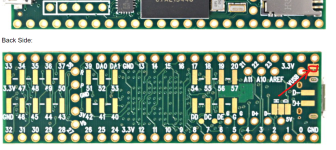
Also you need to cut the small shunt at back of teensy.
After that Teensy is not powered by the PC but only via the 5V input of mainPCB.
The usb link continue to work normaly.
pad to cut.png
 
You need the same GND between the 2 PCB (Not possible in your wiring)
Also you need to cut the small shunt at back of teensy.
After that Teensy is not powered by the PC but only via the 5V input of mainPCB.
The usb link continue to work normaly.
View attachment 1438

I did what you said. I looked at SDA and SCL. it is well connected. the error still exists.
 

Attachments

  • unnamed (4).jpg
    unnamed (4).jpg
    558.3 KB · Views: 12
I2c Scanner:
Code:
// i2c_scanner
// http://playground.arduino.cc/Main/I2cScanner
//
// Version 1
//    This program (or code that looks like it)
//    can be found in many places.
//    For example on the Arduino.cc forum.
//    The original author is not known.
// Version 2, Juni 2012, Using Arduino 1.0.1
//     Adapted to be as simple as possible by Arduino.cc user Krodal
// Version 3, Feb 26  2013
//    V3 by louarnold
// Version 4, March 3, 2013, Using Arduino 1.0.3
//    by Arduino.cc user Krodal.
//    Changes by louarnold removed.
//    Scanning addresses changed from 0...127 to 1...119,
//    according to the i2c scanner by Nick Gammon
//    http://www.gammon.com.au/forum/?id=10896
// Version 5, March 28, 2013
//    As version 4, but address scans now to 127.
//    A sensor seems to use address 120.
// Version 6, November 27, 2015.
//    Added waiting for the Leonardo serial communication.
//
//
// This sketch tests the standard 7-bit addresses
// Devices with higher bit address might not be seen properly.
//

#include <Wire.h>

// BUGBUG::Should put this in WireIMXRT.h
#if defined(__IMXRT1062__)
#define WIRE_IMPLEMENT_WIRE
#define WIRE_IMPLEMENT_WIRE1
#define WIRE_IMPLEMENT_WIRE2
#endif
typedef struct {
  TwoWire *_wire;
  const char * wire_name;
  IMXRT_LPI2C_t * const port;
} wire_list_t;

wire_list_t wireList[] = {
  {&Wire, "Wire", &IMXRT_LPI2C1}
#if defined(WIRE_IMPLEMENT_WIRE1)
  , {&Wire1, "Wire1", &IMXRT_LPI2C3}
#endif 
#if defined(WIRE_IMPLEMENT_WIRE2)
  , {&Wire2, "Wire2", &IMXRT_LPI2C4}
#endif
#if defined(WIRE_IMPLEMENT_WIRE3)
  , {&Wire3, "Wire3"}
#endif
};
const uint8_t wirelist_count = sizeof(wireList) / sizeof(wireList[0]);


void setup(void)
{
  for (uint8_t wirelist_index = 0; wirelist_index < wirelist_count; wirelist_index++) {
    wireList[wirelist_index]._wire->begin();
  }
  Serial.begin(9600);
  while (!Serial);
  Serial.println(F("I2C Scanner\n"));
}


void loop(void)
{
  byte error, address;
  int nDevices;

  for (uint8_t wirelist_index = 0; wirelist_index < wirelist_count; wirelist_index++) {
    IMXRT_LPI2C_t * const port = wireList[wirelist_index].port;
    Serial.print(F("Scanning("));
    Serial.print(wireList[wirelist_index].wire_name);
    Serial.println(F(")..."));
    nDevices = 0;
    for (address = 1; address < 127; address++) {
      // The i2c_scanner uses the return value of
      // the Write.endTransmisstion to see if
      // a device did acknowledge to the address.
      wireList[wirelist_index]._wire->beginTransmission(address);
      error = wireList[wirelist_index]._wire->endTransmission();

      if (error == 0) {
        Serial.print(F("Device found at address 0x"));
        if (address < 16) {
          Serial.print("0");
        }
        Serial.print(address, HEX);
        Serial.print("  (");
        printKnownChips(address);
        Serial.println(")");

        nDevices++;
      } else if (error == 4) {
        Serial.print(F("Unknown error at address 0x"));
        if (address < 16) {
          Serial.print("0");
        }
        Serial.print(address, HEX);
        Serial.printf("MCR:%x MSR:%x, MIER:%x MDER:%x MCFGR0:%x MDMR:%x MCCR0:%x\n",
          port->MCR, port->MSR, port->MIER, port->MDER, port->MCFGR0, port->MDMR, port->MCCR0);
      }
    }
    if (nDevices == 0) {
      Serial.println(F("No I2C devices found\n"));
    } else {
      Serial.println(F("done\n"));
    }
  }
  delay(10000);           // wait 10 seconds for next scan
}


void printKnownChips(byte address)
{
  // Is this list missing part numbers for chips you use?
  // Please suggest additions here:
  // https://github.com/PaulStoffregen/Wire/issues/new
  switch (address) {
    case 0x00: Serial.print(F("AS3935")); break;
    case 0x01: Serial.print(F("AS3935")); break;
    case 0x02: Serial.print(F("AS3935")); break;
    case 0x03: Serial.print(F("AS3935")); break;
    case 0x0A: Serial.print(F("SGTL5000")); break; // MCLK required
    case 0x0B: Serial.print(F("SMBusBattery?")); break;
    case 0x0C: Serial.print(F("AK8963")); break;
    case 0x10: Serial.print(F("CS4272")); break;
    case 0x11: Serial.print(F("Si4713")); break;
    case 0x13: Serial.print(F("VCNL4000,AK4558")); break;
    case 0x18: Serial.print(F("LIS331DLH")); break;
    case 0x19: Serial.print(F("LSM303,LIS331DLH")); break;
    case 0x1A: Serial.print(F("WM8731")); break;
    case 0x1C: Serial.print(F("LIS3MDL")); break;
    case 0x1D: Serial.print(F("LSM303D,LSM9DS0,ADXL345,MMA7455L,LSM9DS1,LIS3DSH")); break;
    case 0x1E: Serial.print(F("LSM303D,HMC5883L,FXOS8700,LIS3DSH")); break;
    case 0x20: Serial.print(F("MCP23017,MCP23008,PCF8574,FXAS21002,SoilMoisture")); break;
    case 0x21: Serial.print(F("MCP23017,MCP23008,PCF8574")); break;
    case 0x22: Serial.print(F("MCP23017,MCP23008,PCF8574")); break;
    case 0x23: Serial.print(F("MCP23017,MCP23008,PCF8574")); break;
    case 0x24: Serial.print(F("MCP23017,MCP23008,PCF8574")); break;
    case 0x25: Serial.print(F("MCP23017,MCP23008,PCF8574")); break;
    case 0x26: Serial.print(F("MCP23017,MCP23008,PCF8574")); break;
    case 0x27: Serial.print(F("MCP23017,MCP23008,PCF8574,LCD16x2,DigoleDisplay")); break;
    case 0x28: Serial.print(F("BNO055,EM7180,CAP1188")); break;
    case 0x29: Serial.print(F("TSL2561,VL6180,TSL2561,TSL2591,BNO055,CAP1188")); break;
    case 0x2A: Serial.print(F("SGTL5000,CAP1188")); break;
    case 0x2B: Serial.print(F("CAP1188")); break;
    case 0x2C: Serial.print(F("MCP44XX ePot")); break;
    case 0x2D: Serial.print(F("MCP44XX ePot")); break;
    case 0x2E: Serial.print(F("MCP44XX ePot")); break;
    case 0x2F: Serial.print(F("MCP44XX ePot")); break;
    case 0x33: Serial.print(F("MAX11614,MAX11615")); break;
    case 0x34: Serial.print(F("MAX11612,MAX11613")); break;
    case 0x35: Serial.print(F("MAX11616,MAX11617")); break;
    case 0x38: Serial.print(F("RA8875,FT6206,MAX98390")); break;
    case 0x39: Serial.print(F("TSL2561, APDS9960")); break;
    case 0x3C: Serial.print(F("SSD1306,DigisparkOLED")); break;
    case 0x3D: Serial.print(F("SSD1306")); break;
    case 0x40: Serial.print(F("PCA9685,Si7021")); break;
    case 0x41: Serial.print(F("STMPE610,PCA9685")); break;
    case 0x42: Serial.print(F("PCA9685")); break;
    case 0x43: Serial.print(F("PCA9685")); break;
    case 0x44: Serial.print(F("PCA9685, SHT3X")); break;
    case 0x45: Serial.print(F("PCA9685, SHT3X")); break;
    case 0x46: Serial.print(F("PCA9685")); break;
    case 0x47: Serial.print(F("PCA9685")); break;
    case 0x48: Serial.print(F("ADS1115,PN532,TMP102,LM75,PCF8591")); break;
    case 0x49: Serial.print(F("ADS1115,TSL2561,PCF8591")); break;
    case 0x4A: Serial.print(F("ADS1115")); break;
    case 0x4B: Serial.print(F("ADS1115,TMP102,BNO080")); break;
    case 0x50: Serial.print(F("EEPROM,FRAM")); break;
    case 0x51: Serial.print(F("EEPROM")); break;
    case 0x52: Serial.print(F("Nunchuk,EEPROM")); break;
    case 0x53: Serial.print(F("ADXL345,EEPROM")); break;
    case 0x54: Serial.print(F("EEPROM")); break;
    case 0x55: Serial.print(F("EEPROM")); break;
    case 0x56: Serial.print(F("EEPROM")); break;
    case 0x57: Serial.print(F("EEPROM")); break;
    case 0x58: Serial.print(F("TPA2016,MAX21100")); break;
    case 0x5A: Serial.print(F("MPR121")); break;
    case 0x60: Serial.print(F("MPL3115,MCP4725,MCP4728,TEA5767,Si5351")); break;
    case 0x61: Serial.print(F("MCP4725,AtlasEzoDO")); break;
    case 0x62: Serial.print(F("LidarLite,MCP4725,AtlasEzoORP")); break;
    case 0x63: Serial.print(F("MCP4725,AtlasEzoPH")); break;
    case 0x64: Serial.print(F("AtlasEzoEC")); break;
    case 0x66: Serial.print(F("AtlasEzoRTD")); break;
    case 0x68: Serial.print(F("DS1307,DS3231,MPU6050,MPU9050,MPU9250,ITG3200,ITG3701,LSM9DS0,L3G4200D")); break;
    case 0x69: Serial.print(F("MPU6050,MPU9050,MPU9250,ITG3701,L3G4200D")); break;
    case 0x6A: Serial.print(F("LSM9DS1")); break;
    case 0x6B: Serial.print(F("LSM9DS0")); break;
    case 0x70: Serial.print(F("HT16K33")); break;
    case 0x71: Serial.print(F("SFE7SEG,HT16K33")); break;
    case 0x72: Serial.print(F("HT16K33")); break;
    case 0x73: Serial.print(F("HT16K33")); break;
    case 0x76: Serial.print(F("MS5607,MS5611,MS5637,BMP280")); break;
    case 0x77: Serial.print(F("BMP085,BMA180,BMP280,MS5611")); break;
    case 0x7C: Serial.print(F("FRAM_ID")); break;
    default: Serial.print(F("unknown chip"));
  }
}
 
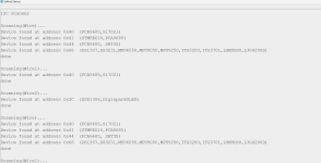
Scanning(Wire)...

Unknown error at address 0x36MCR:1 MSR:2000b01, MIER:0 MDER:0 MCFGR0:0 MDMR:0 MCCR0:1928373b

Unknown error at address 0x37MCR:1 MSR:2000801, MIER:0 MDER:0 MCFGR0:0 MDMR:0 MCCR0:1928373b

Device found at address 0x45 (PCA9685, SHT3X)

Device found at address 0x68 (DS1307,DS3231,MPU6050,MPU9050,MPU9250,ITG3200,ITG3701,LSM9DS0,L3G4200D)

Unknown error at address 0x76MCR:1 MSR:2000b01, MIER:0 MDER:0 MCFGR0:0 MDMR:0 MCCR0:1928373b

Unknown error at address 0x77MCR:1 MSR:2000801, MIER:0 MDER:0 MCFGR0:0 MDMR:0 MCCR0:1928373b

done


Scanning(Wire1)...

Device found at address 0x40 (PCA9685,Si7021)

done


Scanning(Wire2)...

No I2C devices found

I got this.
 
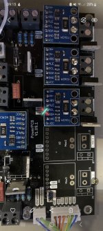
I have attached a picture of how the bridges are.
SDL / SDA is properly connected.

Hello,
did you also swap sda and scl in the firmware. they are different on the inas than on the board. In your case they have to be rewritten. I had to do that too. vg...
 

Attachments

  • Screenshot_20240518_091520_Gallery.jpg
    Screenshot_20240518_091520_Gallery.jpg
    1.5 MB · Views: 12
  • unnamed (1).jpg
    unnamed (1).jpg
    1.2 MB · Views: 11
Hello,
did you also swap sda and scl in the firmware. they are different on the inas than on the board. In your case they have to be rewritten. I had to do that too. vg...

I attached two pictures. If you look, the wire is reversed.
 

Attachments

  • unnamed (6).jpg
    unnamed (6).jpg
    785.1 KB · Views: 7
  • unnamed (5).jpg
    unnamed (5).jpg
    848.9 KB · Views: 8
You can test in the 2 direction without risk, So try to reverse again !!!!
Scanning(Wire)...
Device found at address 0x68 (DS1307,DS3231,MPU6050,MPU9050,MPU9250,ITG3200,ITG3701,LSM9DS0,L3G4200D)
done

Scanning(Wire1)...
No I2C devices found

Scanning(Wire2)...
No I2C devices found


I reverse the wires and this is what I get
 
Scanning(Wire)...
Here what you need to see when you use the I2C Scanner sketch:

on I2C0
0x40 INA226 bat
0x41 INA226 motor l or r
0x44 INA226 motor l or r
0x68 IMU

on I2C1
0x40 INA226 mow

on I2C2
0x3c Oled screen optional

i2c pcb 1.3.png
 
Here what you need to see when you use the I2C Scanner sketch:

on I2C0
0x40 INA226 bat
0x41 INA226 motor l or r
0x44 INA226 motor l or r
0x68 IMU

on I2C1
0x40 INA226 mow

on I2C2
0x3c Oled screen optional

View attachment 1459

Whatever I try, I always get this...

Scanning(Wire)...
Unknown error at address 0x36MCR:1 MSR:2000b01, MIER:0 MDER:0 MCFGR0:0 MDMR:0 MCCR0:1928373b
Unknown error at address 0x37MCR:1 MSR:2000801, MIER:0 MDER:0 MCFGR0:0 MDMR:0 MCCR0:1928373b
Device found at address 0x45 (PCA9685, SHT3X)
Device found at address 0x68 (DS1307,DS3231,MPU6050,MPU9050,MPU9250,ITG3200,ITG3701,LSM9DS0,L3G4200D)
Unknown error at address 0x76MCR:1 MSR:2000b01, MIER:0 MDER:0 MCFGR0:0 MDMR:0 MCCR0:1928373b
Unknown error at address 0x77MCR:1 MSR:2000801, MIER:0 MDER:0 MCFGR0:0 MDMR:0 MCCR0:1928373b
done

Scanning(Wire1)...
Device found at address 0x40 (PCA9685,Si7021)
done

Scanning(Wire2)...
No I2C devices found
 
Back
Top