Matrix MOW800

Now the only problem is that the INA for the motor on the right (power) does not show anything, although it is new and is also found via the i2c scanner, and the INA for the MOW motor shows just over 100W.
PowerPCB is completely new and all INA are new, even the motor driver has already been exchanged for a new one.
 
Welche Pins nutzt Du vom Teensy für die Treiberansteuerung?
Gibt es bei den #define‘s vielleicht eine Doppelbelegung. Ich habe gerade ein Problem mit der internen Temperaturmessung, die mir meinen pinBattery überbelegt. Durch einen vergleichbaren “Fehler“ könnte dein Treibersignal verfälscht werden.
 
Der INA funktioniert jetzt, die Brücke für die Adresse war nicht gesetzt.
Problem ist immer noch der Mähmotor, ich habe jetzt PWMmin auf 50 und max auf 60. Jetzt läuft der Motor laut PfodApp bei 80W.
Die Pins sind alle original, so wie sie in der Software gesetzt sind, da habe ich nichts verändert.
 
Yay, he's driving again.
Still a lot of adjustments and tests to do.
The motors are hard to adjust, it keeps showing motor overload for the right motor, maybe I'll change it again.
The housing is very wobbly and the bumpers always come loose, the rubber bearings need to be stiffened.
It also doesn't like to follow the perimeter to charging station. It always goes down again.

2 new Videos:

 
Great Sascha to see it running. You haven't any HR-SR04 on it, have you ? It wouldn't try to climb on the tree... ?
 
@Bernard
I just noticed that the new INA have a resistor of R100, the old ones only had a R010. Do I have to adjust this in the software?
 
Yes, I think I do need to adjust this.
void setup robot:
Code:
// Calibrate INA226. Rshunt = 0.01 ohm, Max excepted current = 4A
ChargeIna226.calibrate(0.02, 4);
MotLeftIna226.calibrate(0.02, 4);
MotRightIna226.calibrate(0.02, 4);

Change to 0.1 I think. I will test
 
@Bernard
I just noticed that the new INA have a resistor of R100, the old ones only had a R010. Do I have to adjust this in the software?
It's possible to change the calibration in software :
Code:
 ChargeIna226.calibrate(0.02, 4);
    MotLeftIna226.calibrate(0.02, 4);
    MotRightIna226.calibrate(0.02, 4);

But with R100 you can only measure less than 1 A

So replace the resistor by R010 or you are going to destroy the INA226 !
 
Ok, then I'll have to see where I can get them. Do you know what size they are?
Is it possible that my wattage values are so high?
 
No no ultrasonic sensors. I'm waiting for your mounts :cool:
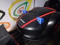
I thought about something like that. I will add a rubber plate to protect the sensor PCB from water and for a perfect fit with the body.
Also the sensor PCB will be spayed with isolation spray.
The blue color is the petg I had to test; I will print thoseones in black petg.
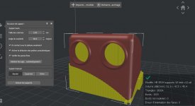
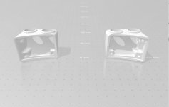
It must be printed with supports as on the picture.
They will be screwed on.
 

Attachments

  • IMG_20220420_202847_resized_20220420_082921936(1).jpg
    IMG_20220420_202847_resized_20220420_082921936(1).jpg
    495.9 KB · Views: 9
  • print.jpg
    print.jpg
    117.1 KB · Views: 10
  • HR-SR04 supports V6 test v23 miror.zip
    HR-SR04 supports V6 test v23 miror.zip
    7 MB · Views: 4
  • fix supports.jpg
    fix supports.jpg
    55 KB · Views: 9
Looks good.
I found an old USB camera, let's see if it works with the Raspi.
If not, I'll order a new one, they don't cost that much.
 
Looks good.
I found an old USB camera, let's see if it works with the Raspi.
If not, I'll order a new one, they don't cost that much.
well the prob is not the cam... but unfortunately the Raspi... I don't have 150€ to spend in a RPI4 for now.
 
Changing the resistors is not fun...

So resistors are changed, now watts fit for the MOW motor ~10W.
The battery indicator in the PfodApp also matches the measured value with a multimeter.

Odometry is now also set as well as possible.
180 and 360 degree rotation is almost perfect. At 3 meters, however, it only drives 2.80m.
Now I just have to test whether it now follows the wire and drives in and out of the charging station.

Update the software and then I can hopefully mow soon.
 
I thought about something like that. I will add a rubber plate to protect the sensor PCB from water and for a perfect fit with the body.
Also the sensor PCB will be spayed with isolation spray.
The blue color is the petg I had to test; I will print thoseones in black petg.
It must be printed with supports as on the picture.
They will be screwed on.
Remember that sonar are not really reliable :oops: ,.I spend a lot of time on it and you need to order 10 of them to have 3 with a correct detection. other detect objet when nothing in front .
 
Now I just have to test whether it now follows the wire and drives in and out of the charging station.
For tracking :
Put the mower in OFF near the perimeter and move it by hand across the wire
Into setting perimeter:
Take a look at Mag and set this value into Perimeter MAG MAX VALUE (4000 in my mower)
Set a very low speed into tracking max speed (test with 20)
You can leave other setting at factory value.

For docking RFID help a lot with a reduce speed tag 1 meter before station.
 
Last time I looked, MAG was between 7000-8000 can that be or is that too much?
I have not installed RFID yet
 
I just uploaded the latest version from your github after adjusting my config and wanted to set the MOW engine.
But when I turn Testing ON, nothing happens. Actual PWM remains at 0?
 
Back
Top