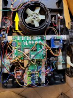
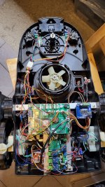
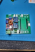
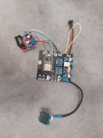
And the comstruction works continues  The next question is about the bumper sensor.
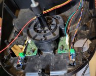
My idea is to use the original Indego Bumper Sensor. This is a hall effect sensor wit a magnet in the bottom of a joystick over it.
The sensor should be the Allegro A1324 in SOT23 package. I think the logic circuit on the PCB invert the output signal of these sensor.
If the magnet over the hall sensor (no bump), the output is low (around 0V). If the joystick pushed, the magnet goes away from the hall sensor (bump), the output pin (blue wire) on the Indego PCB gives +2,5V output.
Some pictures of this solution:
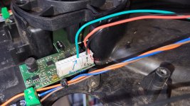
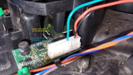
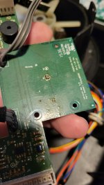
I dont know, if the output pin of the hall sensor PCB can be connected direct to the bumper pin on the Teensy and the pin can be inverted?
Maybe a pulldown activate on the Teensy pin. the 3.3V should be recognized as HIGH.
Or, I think a bit safer solution with add a small transistor, I can use it as a NO switch (same as microswitch): take a look to the PDF.
I think this second solution with the transistor will be effectiver and maybe quicker response. And also safer for the pin on Teensy.

The second question: this only one bumper sensor reacts overall on the chassis. Can the bumper signal evaluate together with the current state of the mower?
That means, if the mower drives forward and the bumper react, the mower stop and will drive backwards. And the bumper signal by reverse drive react in a forward mowement?
I hope you understand my bad english what I mean. Thanks!
My idea is to use the original Indego Bumper Sensor. This is a hall effect sensor wit a magnet in the bottom of a joystick over it.
The sensor should be the Allegro A1324 in SOT23 package. I think the logic circuit on the PCB invert the output signal of these sensor.
If the magnet over the hall sensor (no bump), the output is low (around 0V). If the joystick pushed, the magnet goes away from the hall sensor (bump), the output pin (blue wire) on the Indego PCB gives +2,5V output.
Some pictures of this solution:


I dont know, if the output pin of the hall sensor PCB can be connected direct to the bumper pin on the Teensy and the pin can be inverted?
Maybe a pulldown activate on the Teensy pin. the 3.3V should be recognized as HIGH.
Or, I think a bit safer solution with add a small transistor, I can use it as a NO switch (same as microswitch): take a look to the PDF.
I think this second solution with the transistor will be effectiver and maybe quicker response. And also safer for the pin on Teensy.
The second question: this only one bumper sensor reacts overall on the chassis. Can the bumper signal evaluate together with the current state of the mower?
That means, if the mower drives forward and the bumper react, the mower stop and will drive backwards. And the bumper signal by reverse drive react in a forward mowement?
I hope you understand my bad english what I mean.

