Hello everyone,
In this thread I will be collect the experience with the rebuild a Bosch Indego connect (gen. 1) with the Teensy board.
Why:
- I find the hardwre of the Indego very good, also for big garden over 500m2
- I have allready thre of these Indegos with broken mainboard.
My Goals:
- to use most of the parts of the Indego, because I have a lot of these parts.
- the final function of the Teensy rebuild should have a very similarly scope of the original Indego.
- to have a low budget solution and rescue a lot of the scrap parts.
Here some pictures to the beginning:


My build based on a PowerPCBv1.09 and MainPCBv1.03. For the first try I will use a L298N driver for the brushed motors.
From the Indego LiOn battery (9S / 36V) I will cut two of the cells, so I will have a 7S/24V battery.
The mower motor is a 27V motor, so these will be ok. The driver motors are 36V but I have checked with 24V, the wheels have a speed of appr. 1,8km/h.
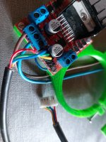
I will try to use the original Indego odometry on the motors. (red arrows) These are two hall sensors (Anachip AH175). I think now these have a similarly function as the KY-003 sensors. (An open collector transistor to pull down the signal of the Teensy odometryPin.
I will use only one of them because thru the gear translation, the hall sensors have appr. 2400 level changes (1200 rising and 1200 falling) in one wheel revolution.
(I hope my idea with this odometry will work. We will see.) Here the test with the oszilloscope of the hall sensors.

Now in the next posts I will need a lot of help to bring this guy to live.")
The Teensy board is programmed, but i have only a Serial consol acess to it.
Base is the RL2000 model with adoptions in the mover.h:
Is it possible that the not calibrated IMU stop the motors? I can not drive the motors. Only a quiet squeaking comes if i try to test the motors over the console.
The mower will be powered at the moment with my bench power supply (25V), because the battery waiting for the rebuild to 7S.
At the moment I dont have accsess with the pfodApp to the ESP32 board. NoBT no WIFI.
This is the biggest problem at the moment. I try actually a lot of boards in Arduino IDE.
What software is better to use in the GitHub: "ESP32_BT_Passerelle" or "ESP32_WIFI_Passerrelle" ???
That for the first and we will se when the Robot comes to live...
In this thread I will be collect the experience with the rebuild a Bosch Indego connect (gen. 1) with the Teensy board.
Why:
- I find the hardwre of the Indego very good, also for big garden over 500m2
- I have allready thre of these Indegos with broken mainboard.
My Goals:
- to use most of the parts of the Indego, because I have a lot of these parts.
- the final function of the Teensy rebuild should have a very similarly scope of the original Indego.
- to have a low budget solution and rescue a lot of the scrap parts.
Here some pictures to the beginning:
My build based on a PowerPCBv1.09 and MainPCBv1.03. For the first try I will use a L298N driver for the brushed motors.
From the Indego LiOn battery (9S / 36V) I will cut two of the cells, so I will have a 7S/24V battery.
The mower motor is a 27V motor, so these will be ok. The driver motors are 36V but I have checked with 24V, the wheels have a speed of appr. 1,8km/h.
I will try to use the original Indego odometry on the motors. (red arrows) These are two hall sensors (Anachip AH175). I think now these have a similarly function as the KY-003 sensors. (An open collector transistor to pull down the signal of the Teensy odometryPin.
I will use only one of them because thru the gear translation, the hall sensors have appr. 2400 level changes (1200 rising and 1200 falling) in one wheel revolution.
(I hope my idea with this odometry will work. We will see.) Here the test with the oszilloscope of the hall sensors.
Now in the next posts I will need a lot of help to bring this guy to live.
The Teensy board is programmed, but i have only a Serial consol acess to it.
Base is the RL2000 model with adoptions in the mover.h:
and://**************************************************************
// ------- select one platform type -------------------
//**************************************************************
//#define MI632
//#define YARDFORCE
#define RL2000
//#define MOW800
//**************************************************************
// ------- select one mainPCB -------------------
//**************************************************************
//#define PCB_V101
#define PCB_V103
Here the consol output:#if defined (RL2000) // here all setting for YARDFORCE
//*****************possible list of motor driver set to :****************
// 1 for brushless ZS-X11H v1 Driver
// 2 for DC L298N Driver
// 3 for DC BTS7960 Driver
#define LEFT_MOTOR_DRIVER 2 //never mix BL and DC on drive motor
#define RIGHT_MOTOR_DRIVER 2
#define MOW_MOTOR_DRIVER 2
#define BUMPER_IS_SWITCH true // set to true if the bumper is a single ON/OFF switch
#define BUMPER_REAR_EXIST false // set to true to manage the rear bumper connected on CAN3 J20 connector
#define BUMPER_ARE_NORMALY_CLOSED false // set to true if the bumper contact is closed when nothing is hit
#define START_BUTTON_IS_NC false //if button is normaly closed
// mower can have a cover that stop the mowing cycle but power still on the PCB,mower only start after closing the cover
// start button is under cover , so after push the start button you have 10 seconde to close cover and mower start
// openning the cover stop mowing cycle
#define MOWER_HAVE_SECURITY_COVER false // mower can have a cover that stop the mowing cycle but power still on the PCB,mower only start after closing the cover
#define INA226_MOW2_PRESENT false
#define INA226_MOW3_PRESENT false
#define ODOMETRY_ONLY_RISING false
#endif
SETUP
++++++++++++++ Start Robot Setup at 742.00 ++++++++++++
Initialise date time library
RTC has set the system time
------------------- Initializing SD card... ---------------------
SD Card failed, or not present
Version : 1.493-Teensyber
Pfod connection initialisation at : 19200
Load ErrorData Address Start= 500.00 Stop= 522.00
UserSettings OK from Address : 2000.00 To 2500.00
Load Stats Adress Start = 800.00 Stop = 826.00
IMU Warning: no calib data
-------- IMU CALIBRATION --------
ACCEL GYRO MPU6050 OFFSET ax: 376 ay: -1768 az: 1512 gx: 91 gy: 12 gz: -2
COMPASS OFFSET X.Y.Z AND SCALE X.Y.Z
comOfs=0.00,0.00,0.00
comScale=2.00,2.00,2.00
.
--------------------------------- GYRO ACCEL INITIALISATION ---------------
MPU6050 connection successful
52
Initializing DMP...
Enabling DMP... Packet size 28
Wait 3 secondes to stabilize the Drift
AccelGyro Yaw: 0.00--------------------------------- IMU READY ------------------------------
------- Initialize Perimeter Setting -------
Begin setup adc0 on pin:23
End setup adc0
Try to Start adc0 Timer Interrupt
adc0 Timer Interrupt Started
START
Mower 1.493-Teensyber
Config: RL2000
press...
d for menu
v to change console output (sensor counters, values, perimeter etc.)
off
Starting Ina226 current sensor
Checking ina226 current sensor connection
Ina226 Begin OK
Ina226 Configure OK
Ina226 Calibration OK
Watchdog configuration start
Watchdog configuration Finish
Setup finish
MAIN MENU:
1=test motors
To test odometry --> use Arduremote
3=communications menu
5=Deactivate and Delete GYRO calibration : To calibrate GYRO --> use Arduremote Do not move IMU during the Calib
6=Deactivate and Delete Compass calibration : To calibrate Compass --> use Arduremote start/stop
9=save user settings
l=load factory settings: Do not save setting before restart the mower
r=delete robot stats
x=read settings
e=delete all errors
0=exit
testing left motor (forward) half speed...
testing left motor (reverse) full speed...
testing right motor (forward) half speed...
testing right motor (reverse) full speed...
warning Watchdog detect that loops take too long duration
Tennsy can automaticly reboot if issue is not reset
Is it possible that the not calibrated IMU stop the motors? I can not drive the motors. Only a quiet squeaking comes if i try to test the motors over the console.
The mower will be powered at the moment with my bench power supply (25V), because the battery waiting for the rebuild to 7S.
At the moment I dont have accsess with the pfodApp to the ESP32 board. NoBT no WIFI.
This is the biggest problem at the moment. I try actually a lot of boards in Arduino IDE.
What software is better to use in the GitHub: "ESP32_BT_Passerelle" or "ESP32_WIFI_Passerrelle" ???
That for the first and we will se when the Robot comes to live...


")


