I did this already, but this is onla a short time solution. I tried to remove the mounting plate, but cannot disassemble the gear from the shaft. The motor is a standard size, but the correct gear is needed.A little bit of oil from both sides?
You are using an out of date browser. It may not display this or other websites correctly.
You should upgrade or use an alternative browser.
You should upgrade or use an alternative browser.
RL2000 with problems
- Thread starter SefanH
- Start date
I tried to remove it with a special tool, but no success.The gear ist just pressed, I think.
@Sascha Bis jetzt funktioniert das prima. Ich würde aber mir noch etwas überlegen, wie man die ganze 24V Strecke, wo auch der DC/DC-Wandler dran hängt, vor Überspannung zu schützen. Das würde sich auch gut für den Teensy und das GPS machen.Funktioniert das so bei dir? Dann würde ich das in der nächsten PowerPCB anpassen.
Dann kann ich die MBR1045 bei den Ausgängen auch weglassen, da die das eigentlich verhindern sollten.
Im currently on build up an (old and big) Bosch Indego conversion with the Teensy. I think in 1-2 days i will open a new thread with the platform specific questions and solutions.The Q4 was died for sure. This can happen if the GS-Voltage will exceed 24V (datasheet: Vgs max = 20V). I did a change on the power PCB after I had the same problem - see pdf attached. Also the "cheap" Mosfets from Amazon or Ali are not the best quality, better to use it from a qualified source (Conrad, Reichelt, RS...).
The main issue is, that the motors working as a generator if they break or just reduce its speed, this can kill the DC/DC converter too.
By the way: I have noticed the same with the possibly to high GS Voltage on Q2 and Q4! I have added simple a 2k2 Resistor between the collector of Q1 and the waypoint to the gate of Q2. So I got here a very simply voltage divider (4k7 to 2k2). The current will be a bit lower through Q1, but i think its ok. The GS voltage will be so always below 20V. The same concept by Q4. Additionally by Q4 between Pin2 of J9 and ground also an 2k2 resistor for the manualy start.
SefanH
Well-known member
Mein RL2000 ist schon wieder tot. Keine Spannung am DCDC-Wandler, wird wohl wieder der IRF9540 (Q4) sein. Ich denke ich nehme mal einen etwas stärkeren MOSFET, den IRF5210. Ich werde einen großen kühlkörper verwenden. Hierzu verbinde ich den IRF5210 mit Kabeln mit der Platine.
Q3 wird auch wieder defekt sein, der Mäher startet wieder, ohne dass der Knopf gedrückt wird. Ich werde wohl bei beiden (Q3 und Q4) den Vorschlag von Boesling umsetzen und die Widerstände samt der Z-Diode verbauen.
My RL2000 is dead again. No voltage on the DCDC converter, it must be the IRF9540 (Q4) again. I think I'll use a slightly stronger MOSFET, the IRF5210. I'll use a large heat sink. To do this, I'll connect the IRF5210 to the circuit board with cables.
Q3 will also be defective again, the mower will start again without the button being pressed. I'll probably implement Boesling's suggestion for both (Q3 and Q4) and install the resistors along with the Z-diode.
Ich habe in meinem Idego-Teensy mit powerPCB1.09 auch die IRF 5210 eingebaut. (mit relativ großem Kühlkörper an Q4) Bei mir ist alles eiskalt.
ABER! Ich denke das wichtigste ist, dass die GS Spannung auf irgendeine Art runterdividiert wird! Laut Datenblatt max. 20V!
Das habe ich hier weiter oben (post #25) beschrieben: GS Voltage on Q2 and Q4 (ich habe ohne Z-Diode nur mit einem zusätzlichen 2k2 Widerstand gelöst) Diese einfache Spannungsteiler funktioniert für mich bestens. Leider müssen dazu 1-2 Leiterbanen an der PCB etwas modifiziert/gekappt werden. Bei Q4 habe ich einen 2k2 Widerstand auch in den Schalter integriert.
I also installed the IRF 5210 in my Idego-Teensy with powerPCB1.09. (with a relatively large heat sink on Q4) Everything is ice cold for me.
BUT! I think the most important thing is that the GS voltage should be divided down in some way! According to the data sheet, max. 20V!
I described this above (post #25): GS Voltage on Q2 and Q4 (I solved without Z-diode only with an additional 2k2 resistor)
This simple voltage divider works perfectly for me. Unfortunately, 1-2 tracks on the PCB have to be cutted/modified slightly.
For Q4 I integrated also a 2k2 resistor into the switch.
Do you have idea on how this append.No voltage on the DCDC converter, it must be the IRF9540 (Q4) again.
What is the full sense read when mowing ?
Very high grass ??
Emergency at full mow speed ??
Mow motor stuck immediatly by something ??
Etc....
Der IRF9540 reicht vollkommen aus, Problem ist nur die GS-Spannung, wie oben beschrieben. Seit dem Umbau mit dem Spannungsteiler und den Z-Dioden, hatte ich keinen Ausfall mehr.
The IRF9540 is perfectly adequate, the only problem is the GS voltage, as described above. Since the conversion with the voltage divider and the Z diodes, I have not had any more failures.
The IRF9540 is perfectly adequate, the only problem is the GS voltage, as described above. Since the conversion with the voltage divider and the Z diodes, I have not had any more failures.
SefanH
Well-known member
So, den umbau habe ich jetzt gemacht, war nicht ganz leicht. Ich habe die Power PCB V1.6. Vom Papier auf die Platine sind da doch einige Hürden zu nehmen. Morgen werde ich es testen.
So, I've now made the conversion, it wasn't easy. I have the Power PCB V1.6. There are a few hurdles to overcome when getting from paper to the circuit board. I'll test it tomorrow.
So, I've now made the conversion, it wasn't easy. I have the Power PCB V1.6. There are a few hurdles to overcome when getting from paper to the circuit board. I'll test it tomorrow.
I would try to start the Teensy alone on the desk. For this you can solder/bridge the 5V connection pads on the back of the Teensy and supply it over the usb cable (very small place there!), or you can supply with external 5V on the 5V pin. On the serial monitor should be give a start sequence.
If the Teensy starts, than the problem is on the board or the ESP32.
If the Teensy wont start alone, then the problem is maybe on the teensy.
edit: anyway, after unplugged the teensy, on the main pcb you can check the 3.3v and 5v pins for short (or low resistance) to grund.
If the Teensy starts, than the problem is on the board or the ESP32.
If the Teensy wont start alone, then the problem is maybe on the teensy.
edit: anyway, after unplugged the teensy, on the main pcb you can check the 3.3v and 5v pins for short (or low resistance) to grund.
I don't have an RL2000. I have only Indego's.
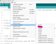
The CPU frequency can be adjusted in the Arduino in the board select menu before the code will be uploaded. You can try to reduce it to 528MHz, but maybe you will get problems with the robot mowement. I haven't really tried it.
On my first Teensy I have setted the max temp to 75°C. By appr. 35°C ambient I have got max 70-72°C in the Indego case, with a little heatsink on the Teeensy CPU.
Over 35°C ambient I dont let run the mower. I think its not necessary.
I suppose you use TEENSYBER ?After a few attempts, I started the teensy a few times with the 3.3v from the ESP, everything is working again... I don't know why!? Now I'll have to keep testing and find the right settings.
How did you set up your RL2000? Motor, ODO?
For temp you can reduce frequency in arduino ide

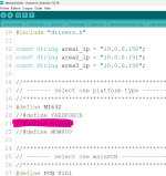
To setup the firmware into mower.h:
Uncomment RL2000 and comment out MI632
Do not forget the PCB version 101 or 103
Now using Pfod do all the odo test and adjust according your need.
and take a look at wiki.
AzuritBer Firmware (English) – www.wiki.ardumower.de

