ZS-X11H Brushless Motor Driver

Hello all,
today i fineshed my research of decoding the Hall Impulses of a brushless Motor with the Raspberry Pi. The challange was that all Hall Tics where counted with a freuquenz of 850Hz per Motor. I found the pigpio library wich is able to run as domain in the background an checks the GPIOs frequently. Now I will solder this on an pcb board and build it in a old Robolino Mower. If its wanted i can post the code. Attached you will find a short video, sorry the voice is in german language

View attachment brushless-2023-10-27_H9iHSAvt.mp4
 
Can you make a picture?
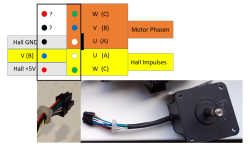
here the first motor, it is a LINIX 60ZWN24-30L brushless Blade Motor. I checked all Wires and if I connect them to the driver in this order as written the motor runs. But the red and black wire I have now Idea, the resistance between the wire is around 12kOhm.
1698509303019.png
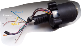
I do not know the type of the second motor. I found him in a robolinho. Here is the same. If i connect the wires in the right way the motor runs but the function of the 2 wires pink and brown I have no Idea there is no resistance between them
Any Idea?
1698509775037.png
 
Ja guck mal hier:

Nein, sehe gerade, das es mit den Kabeln nicht zusammen passt.
 
zerlegen könnte ich vielleicht den kleineren der beiden Cutter Motore, definitiv haben beide aber andere Encoder verbaut.
Dann werde ich das einfach mal so belassen. Vielleicht finde ich noch einmal einen Cutter Motor in der elektronischen Bucht:
Die beiden die ich jetzt noch habe sind schon fest für Projekte verplant, da wäre es schade wenn ich aufgrund von Neugier, einen zerstöre,
denn die sind bestimmt auf µMeter genau zusammengebaut.
Aber Danke dass Du geschaut hast.
 
here the first motor, it is a LINIX 60ZWN24-30L brushless Blade Motor. I checked all Wires and if I connect them to the driver in this order as written the motor runs. But the red and black wire I have now Idea, the resistance between the wire is around 12kOhm.
View attachment 1082
I do not know the type of the second motor. I found him in a robolinho. Here is the same. If i connect the wires in the right way the motor runs but the function of the 2 wires pink and brown I have no Idea there is no resistance between them
Any Idea?
View attachment 1083
Possible thermal security .
Check if 12 Kohm change when motor heat.

Always check the working in the 2 direction with a correct torque to be sure the wiring is in the correct order.
 
Yes, thermal Security this ist possible.
Good Idea! Make sense in Order to Protect the Motor. I will Check this next year in spring.
I can say that the wiring ist okay. The Motor needs 200 - 400mA in free driving. This ist similar to the other Motors
 
Hallo
gestern habe ich in meinem roπLawnMow die PID SW aktualisiert und den Gyro zur Spurhaltung in Betrieb genommen. Den Beitrag im Forum findet ihr hier Der Code folgt demnächst, es steht noch die Fahrt entlang des Perimeterdrahtes an, das habe ich noch nicht implementiert. Alles ist pur Python. Dabei fiel mir gestern auf, dass die ZS-X11H Boards anscheinend in einen Schutz haben, wenn der Motor bestromt wird, aber keine Hall Impulse zurück kommen, z.B. wenn das Rad blockiert. Ich konnte das reproduzieren, aber nur beheben, in dem ich die Betriebsspannung des Moduls kurz ab geschaltet habe und dann wieder ein geschaltet habe. Kennt jemand noch eine andere Lösung?
Wenn nicht würde es bedeuten ich müsste auch die Treiber für die Antriebsräder über einen FET schalten, damit ich die Betriebsspannung kurz unterbrechen kann. SW-mäßig ist das ja kein Problem, bedeutet nur wieder ein stcücken mehr HW.
 
Danke, da ich den 100K am Break schon verschaltet habe teste ich das demnächst noch einmal dem Stop Eingang, der liegt bei mir in der Luft. Vielleicht wäre das dann die Lösung. Ich werde berichten
Danke für den Link, den Artikel kannte ich noch nicht.
 
Hello all,
today i fineshed my research of decoding the Hall Impulses of a brushless Motor with the Raspberry Pi. The challange was that all Hall Tics where counted with a freuquenz of 850Hz per Motor. I found the pigpio library wich is able to run as domain in the background an checks the GPIOs frequently. Now I will solder this on an pcb board and build it in a old Robolino Mower. If its wanted i can post the code. Attached you will find a short video, sorry the voice is in german language

View attachment 1081
Ich sehe bei dem Video das gleiche Problem, welches ich bei meinen Hoverboard-Motoren auch habe: das Geschwindigkeitssignal schwankt zu stark! Die gezählten Ticks sind nicht plausibel. Der Regler schwingt in Folge oder ist bei der erforderlichen Glättung zu langsam. Ich vermute, es liegt an den Interrupts. Vielleicht müßte man einen Teiler vorschalten, damit nicht so viele Impulse gezählt werden müssen, oder es muß ein Decoder ans Rad. (Oder man findet gegebenen Falls die Programmierfehler - was ich persönlich grundsätzlich nie ausschließe)
 
For ZS-X11H :

No particular issue on my side to read the ticks at high precision, so certainly not a driver issue ,(850Hz is not high frequency from interrupt process) Are you sure it's not a MCU issue.

Yes overload can freeze the driver and it's a normal working mode to avoid smoke ;)
I am OK with @EinEinfach: put all pin to low reset the freeze.(maybe need pulldown resistor on some pin to be sure)

In all case it's better to use Power PCB and the firmware always check the motor sense to stop motor before this last overload sense error.
Into teensyber this feature is also used like a Bumper.

You have the same process into DC motor driver MC33926
 
Ich sehe bei dem Video das gleiche Problem, welches ich bei meinen Hoverboard-Motoren auch habe: das Geschwindigkeitssignal schwankt zu stark! Die gezählten Ticks sind nicht plausibel. Der Regler schwingt in Folge oder ist bei der erforderlichen Glättung zu langsam. Ich vermute, es liegt an den Interrupts. Vielleicht müßte man einen Teiler vorschalten, damit nicht so viele Impulse gezählt werden müssen, oder es muß ein Decoder ans Rad. (Oder man findet gegebenen Falls die Programmierfehler - was ich persönlich grundsätzlich nie ausschließe)
Danke Fürst, für Deim Feedback, jetzt ist das VIdeo ja schon etwas älter und in der Zwischenzeit habe ich noch so einige Iterationsschritte gemacht. Aber Du hast recht der Pi (as he is) kann die Tics der Hall Impulse nicht zählen, aber das geht mit der pigpio perfekt. Die Rampen beim Beschleunigen und beim Abbremsen hatte ich codiert. Ansonsten funktioniert es für meine Ansprüche perfekt. Ein wenig struggle ich noch mit den
PID Reglern, obwohl ich die zum Geschwindigkeit konstant halten schon ordentlich hin bekommen habe, konnte man in den anderen Videos denke ich gut sehen. Verbessern muss ich noch die PID Regler zum Kurs halten. und kommende Woche mache ich mich dann an das follow the Wire Project. Und was die SW betrifft ich bin nur ein hobbyiest, so dass ich es auch nie ausschließe dass ich was falsch kodiert habe. Daher gehe ich immer Step by Step vor.
 
For ZS-X11H :

No particular issue on my side to read the ticks at high precision, so certainly not a driver issue ,(850Hz is not high frequency from interrupt process) Are you sure it's not a MCU issue.

Yes overload can freeze the driver and it's a normal working mode to avoid smoke ;)
I am OK with @EinEinfach: put all pin to low reset the freeze.(maybe need pulldown resistor on some pin to be sure)

In all case it's better to use Power PCB and the firmware always check the motor sense to stop motor before this last overload sense error.
Into teensyber this feature is also used like a Bumper.

You have the same process into DC motor driver MC33926
Thx @Bernard and @EinEinfach I will test it with the pins to low, bat I agree with you, I should implement two secure routines,
first the controller sends the a pwm signal to the driver and there are no tics responding during maybe 1s. An emergency off shoud raise.
Second if the current of the motors is to high also an emergency off should raise. It is on my 2do list.
I am happy that you responding to my posts I really appreciate that.
 
Back
Top