Why use?
(...) if you have a big mow motor with a lot of inertia ,the driver can send more than 100 V on it's 24V input if you directly brake it from full speed and destroy some component on the main PCB (not the driver one).
Normally you need a power resistor to absorb the power peak.Or a big capacitor(...)
 forum.roboteers.org
jyqd2021
(...)
This braking function was not yet available on the 2017 PCB. A slight disadvantage here is that the braking current is not regulated and can be much higher than the maximum motor current flowing during acceleration. This can lead to an excessive operating voltage (braking cycle: the motor now acts as a generator, and current flows into the battery via body diodes) and places greater strain on the L-MOSFETs of the three half-bridges, because they then have to short-circuit/dissipate the braking energy. Here, too, the user is responsible for determining the load limits themselves and implementing suitable measures to protect the motor and electronics.
In the low-phases, the short-circuit current flows through the low-phase FETs, and in the high-phases, unfortunately, it flows into the battery—which can lead to excessive voltage across the FETs.
The scheme is derived from:
(...) I've attached a design of a very simple shunt regulator that will do this. The regulation isn't great, but it will shunt more and more current as the voltage increases slightly higher, which is what's important in this case. The Power transistor is one or more big (TO-247 or TO-3P) Darlington NPN power transistor(s) (I modeled it using some discretes built into LTSpice, but I would build it with a Darlington device). The zener provides the working voltage, about 1.3 V higher than the zener voltage (zener breakdown + transistor Vbe). The 10k resistor is necessary to prevent the transistor from conducting due to any leakage through the zener, when the voltage is still below the threshold. The 2 ohm resistor is an arbitrary value for the source resistance of the braking controller
(...)
Not so much components, it very well fit to PowerPCB 1.0 small (except external power resistors):


That scheme was tested using:
Power supply with voltage of 28V and CC limited current for 0,5A. For higher current, Darlington transistor should have been mounted on radiator.
- zener diode 24V, because i don't have higher voltage power supply. In example for 7s lion, that zener voltage should be higher. 7s lion =29,4V when charged. When using 33V zener with tolerance of 5% = 33V-5%= 31,35V that voltage is above 7s configuration.
- BU931P Darlington transistor or other like tip142g
- 10k resistor
- base resistor: tried value 220ohm and without the resistor (both worked, without the base resistor it shunt more current)
-2 ohm 100w power resistor
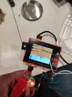
-5w 12V bulbs (Just for testing)
When the voltage is under the 24V (zener voltage) nothing happened.


When the voltage is above: zener breakdown + transistor Vbe. The regulator is starting to work. In that case it drawing 16W that could be delivered by power CC supply (28V 0,5A)
With 2ohm power resistor, no base resistor:

Ideally, that configuration should be tested with higher rating power supply and be heatsinked.
For base resistor in Darlington transistor, usually used 'rule of thumb' hFE value =100 (but could also be readed from transistor datasheet)
There are others similar working shunt regulator, but they have some other drawbacks:
ZS-X11D1 (JYQD2021) Treiber und Sunray
Da es bereits einige User gibt, die positive Erfahrugnen mit dem oben genannte Treiber gemacht haben, wollte ich und @Algo hier unsere Erfahrungen für andere, die evtl. diesen Treiber einsetzten möchten, dokumentieren. Den Treiber gibt es aktuell in der Bucht mit und ohne Hall-Sensor-Eingängen...
forum.ardumower.de
(...) if you have a big mow motor with a lot of inertia ,the driver can send more than 100 V on it's 24V input if you directly brake it from full speed and destroy some component on the main PCB (not the driver one).
Normally you need a power resistor to absorb the power peak.Or a big capacitor(...)
Beiträge von Lars - German Roboteers Association e.V.
forum.roboteers.org
jyqd2021
(...)
This braking function was not yet available on the 2017 PCB. A slight disadvantage here is that the braking current is not regulated and can be much higher than the maximum motor current flowing during acceleration. This can lead to an excessive operating voltage (braking cycle: the motor now acts as a generator, and current flows into the battery via body diodes) and places greater strain on the L-MOSFETs of the three half-bridges, because they then have to short-circuit/dissipate the braking energy. Here, too, the user is responsible for determining the load limits themselves and implementing suitable measures to protect the motor and electronics.
In the low-phases, the short-circuit current flows through the low-phase FETs, and in the high-phases, unfortunately, it flows into the battery—which can lead to excessive voltage across the FETs.
The scheme is derived from:
(...) I've attached a design of a very simple shunt regulator that will do this. The regulation isn't great, but it will shunt more and more current as the voltage increases slightly higher, which is what's important in this case. The Power transistor is one or more big (TO-247 or TO-3P) Darlington NPN power transistor(s) (I modeled it using some discretes built into LTSpice, but I would build it with a Darlington device). The zener provides the working voltage, about 1.3 V higher than the zener voltage (zener breakdown + transistor Vbe). The 10k resistor is necessary to prevent the transistor from conducting due to any leakage through the zener, when the voltage is still below the threshold. The 2 ohm resistor is an arbitrary value for the source resistance of the braking controller
(...)
Not so much components, it very well fit to PowerPCB 1.0 small (except external power resistors):
That scheme was tested using:
Power supply with voltage of 28V and CC limited current for 0,5A. For higher current, Darlington transistor should have been mounted on radiator.
- zener diode 24V, because i don't have higher voltage power supply. In example for 7s lion, that zener voltage should be higher. 7s lion =29,4V when charged. When using 33V zener with tolerance of 5% = 33V-5%= 31,35V that voltage is above 7s configuration.
- BU931P Darlington transistor or other like tip142g
- 10k resistor
- base resistor: tried value 220ohm and without the resistor (both worked, without the base resistor it shunt more current)
-2 ohm 100w power resistor
-5w 12V bulbs (Just for testing)
When the voltage is under the 24V (zener voltage) nothing happened.
When the voltage is above: zener breakdown + transistor Vbe. The regulator is starting to work. In that case it drawing 16W that could be delivered by power CC supply (28V 0,5A)
With 2ohm power resistor, no base resistor:
Ideally, that configuration should be tested with higher rating power supply and be heatsinked.
For base resistor in Darlington transistor, usually used 'rule of thumb' hFE value =100 (but could also be readed from transistor datasheet)
There are others similar working shunt regulator, but they have some other drawbacks:
Protecting electronics from overvoltages from BLDC motor, using shunt (power) resistor.
When the BLDC motor brakes or the power to it is switched off but motor shaft still rotating using inertia (mainly mow motor). The motor producing high voltages that can damage connected electronics. There are many solutions for that problem: -battery pack acting as a buffer that accumulates...
forum.ardumower.de