Generally microcontrollers could have built-in selectable by software, pull-up or pull-down resistors on inputs.
But sometimes there are need for external resistor.

 forums.ni.com
If we know what configuration we need, the circuit is simple:
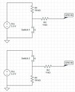
 www.cl.cam.ac.uk
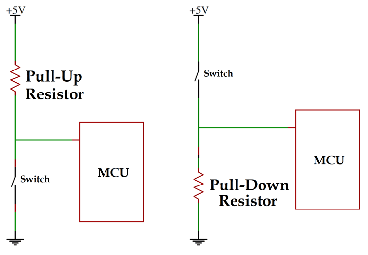
 circuitdigest.com
But what if we dont know yet, for what we will use spare pin in the future? Need pull-up or pull-down configuration?
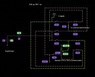
The combined scheme for selectable pull-up or pull-down scheme for digital input:
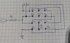
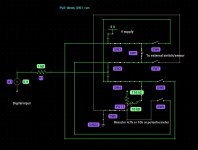
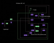
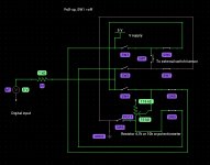
A2, B2 =external sensor/switch
Between C2 and D2 resistor 4,7k, 10k or potentiometer
Pull-down:
A1+A2, B1+B2, C1+C2, D1+D2
Pull-up:
A2+A3, B2+B3, C2+C3, D2+D3
The configuration can be selected on pcb board using jumper or solderable jumper pin pads.
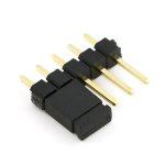
The working principle is shown here:
But sometimes there are need for external resistor.

Digital Input on Raspberry Pi
Attempting simple Digital Input on a Raspberry Pi 2 B, but only pin 7 is responsive to changes in grounding. I'm using a simple jumper cable to take pin 39 ground and connect to the requisite digital pin (40, 11, 12, all the same). all images I've caught online seem to indicate that simply...
If we know what configuration we need, the circuit is simple:

Buttons and Switches - Physical Computing with Raspberry Pi

Pull Up and Pull Down Resistor
What is a pull up and pull down resistor? A Pull-up resistor is used to make the default state of the digital pin as High or to the logic level (in the above image it is 5V) and a Pull-Down resistor does exactly opposite, it makes the default state of the digital pin as Low (0V).
But what if we dont know yet, for what we will use spare pin in the future? Need pull-up or pull-down configuration?
The combined scheme for selectable pull-up or pull-down scheme for digital input:

A2, B2 =external sensor/switch
Between C2 and D2 resistor 4,7k, 10k or potentiometer
Pull-down:
A1+A2, B1+B2, C1+C2, D1+D2
Pull-up:
A2+A3, B2+B3, C2+C3, D2+D3
The configuration can be selected on pcb board using jumper or solderable jumper pin pads.


The working principle is shown here:


