You are using an out of date browser. It may not display this or other websites correctly.
You should upgrade or use an alternative browser.
You should upgrade or use an alternative browser.
TEENSY PCB WIRING
- Thread starter Bernard
- Start date
Nun ich meine das die Arduino MEGA PCB doch für einen Rasenmäher ausreichend schnell sein müßte, denn sie reicht ja alle Mal für einen 3 D Druckjer und der hat ja ganz bestimmt nicht weniger Daten zu verarbeiten und die Motore der Achsen und des Extruders werden doch ständig ein aus und beschleunigt geschalten.Hallo.
Ich benutze Google Übersetzer, um Ihren Beitrag zu verstehen, aber es ist nicht einfach.
Ich kenne rep_al PCB nicht, aber was ich sehe, ist in der Nähe des Arduino-Projekts mit dem ersten PCB-Build 6 oder 7 Jahre später mit Arduino Mega und UNO.
Es ist etwas sehr Gutes und funktioniert gut, aber die Leistung von Arduino Mega ist sehr begrenzt und es ist schwierig, den Motor sehr schnell zu beschleunigen und zu verlangsamen, sodass die Bewegung beim Tracking nicht perfekt glatt ist. Die Decodierung des Perimetersignals benötigt auch CPU-Leistung.
Schauen Sie sich im Netz den Unterschied zwischen MEGA / DUE / Grand Central M4 / und Teensy 4.1 an
Ich weiß nicht, ob der Motorsinn in der rep_al-Hardware gelesen und von Soft verwaltet wird.
Also für mich:
Wenn Sie eine fertige einfache Lösung zum Bauen mit einem 3D-Drucker wünschen, sind REP_AL oder Ardumower in Ordnung.
Wenn Sie einen sehr kostengünstigen Betrieb wünschen (kaufen Sie einen gebrauchten Rasenmäher DENNA L600 oder MI555C oder RL2000 mit guten mechanischen Teilen) und verwenden Sie die Teensy-Leiterplatte.
Wenn Sie eine Herausforderungslösung suchen, verwenden Sie das Artic-Hasen-Chassis mit Teensy-PCB und versuchen Sie, Raspberry Pi AI Vision und die RTK-Lösung darin zu integrieren
Denken Sie daran, dass das Wichtigste das Ziel ist: Eine perfekt geschnittene Rasenfläche
Also möchte ich schon meinen , daß ein Mäher der ja nix weiter zu tun hat als zu schauen ob er wo gegen fährt oder die 3 bis 4 vorhandenen Motore einschaltet oder nicht! Mal abgesehen von der Navigation. Aber die läuft ja über andere Kanäle! Da ist das Arduino ja nur der Ausführende Posten der die Motore steuert.
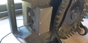
how high is your box?Not sure it's OK .
I have 7 cm on my robomow and DENNA.
Maybe you need to put it in a box out of the chassis like me with the DENNA.
Z.B for fast return to Station or to go to different Areas
Video from Bernhard
Video from Bernhard
SefanH
Well-known member
Odometry 3.3V module
View attachment 159
This picture shows PCB version 1.2?
In version 1.3 it is a little different: R7 + R8 shunt and R1 + R2 not populated?
Or am I making a mistake here?
You are right if you use the 3.3V.This picture shows PCB version 1.2?
In version 1.3 it is a little different: R7 + R8 shunt and R1 + R2 not populated?
Or am I making a mistake here?
ullisun58
Well-known member
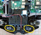
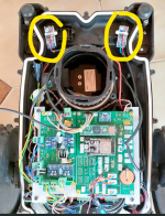
Hi Bernard,Peripheral wiringView attachment 157
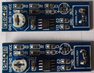
I assume that the Perimeter amplifier will be connect on J13 and J19. How you mounted the pre-amplifier of the coils into your chassis? Du you use a separate case for the 2 PCBs?
Yes do not forget to add 2 resistors to limit the voltage from 5V to 3.3V if you use a PI or teensy. (Coil amplifier is 5V module)I assume that the Perimeter amplifier will be connect on J13 and J19.
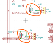
I use the same 3D printed coil support with double tape adhesive inside Viking MI632 and Yardforce chassis.

Here location on mower:
ullisun58
Well-known member
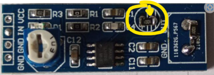
When I read the documentation about the adaption of the pre-amplifier, I understood, that the 100uF should be removed.Why it's not a shunt here ??
https://wiki.ardumower.de/index.php?title=Datei:Perimeter_v2_receiver_circuit.png
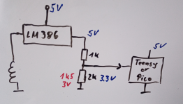
so I replaced the capacitor with the 1K resistor of the voltage divider, and the 2K resistor is located at the picture right side between both solder Pads 1K and 470Ohm in serial.
If there is something wrong? May be I used a wrong schematic?
Thanks that you are asking!
YES.When I read the documentation about the adaption of the pre-amplifier, I understood, that the 100uF should be removed.
https://wiki.ardumower.de/index.php?title=Datei:Perimeter_v2_receiver_circuit.png
so I replaced the capacitor with the 1K resistor of the voltage divider, and the 2K resistor is located at the picture right side between both solder Pads 1K and 470Ohm in serial.
If there is something wrong? May be I used a wrong schematic?
Thanks that you are asking!
I don't have the LM386 schematics, but if you include the 5V/3.3V voltage divisor , it's perfect.
Ok to replace the capacitor by 1K , but for the location of the 2K resistor i don't know
This is OK:

This is BAD :

ullisun58
Well-known member
Hi Bernard,
Thanks for your reply. Yes the 2K is better than a 1.5K but if I need a voltage divider I have to build it like this so far my electronic knowledge.
We have to protect eeensy or the Pico Inputs the maximum voltage is 3.3V as we know. I d
In the meantime I got also 2K resistors, but the 1.5K works also since several month. A 2.7K instead the 1k5 oer 2K resistor is danger.
Since I don't use the Teensy PCB I don't know where J13 or J19 in my schematic below is placed. But it does'nt matter, you answered my orignal question. So I am happy for now.
Best regards Ulli
Thanks for your reply. Yes the 2K is better than a 1.5K but if I need a voltage divider I have to build it like this so far my electronic knowledge.
We have to protect eeensy or the Pico Inputs the maximum voltage is 3.3V as we know. I d
In the meantime I got also 2K resistors, but the 1.5K works also since several month. A 2.7K instead the 1k5 oer 2K resistor is danger.
Since I don't use the Teensy PCB I don't know where J13 or J19 in my schematic below is placed. But it does'nt matter, you answered my orignal question. So I am happy for now.

Best regards Ulli
YES.
I don't have the LM386 schematics, but if you include the 5V/3.3V voltage divisor , it's perfect.

